turn a drawing into a 3d model fusion 360
Introduction: Plow a 2D Epitome Into a 3D Model
Ever want to have a 2d image and plow it into a 3D model? This instructable will bear witness you how with a free script and Fusion 360.
What You'll Demand
Fusion 360 (Mac / Windows)
What You'll Do
- Download and install Fusion 360. Click hither to sign up for free as a Hobbyist / Enthusiast / Startup or as a Student or Educator.
- Get a quick orientation of the user interface.
- Download and install a script that will let y'all plough a 2nd epitome into a 3D surface.
- Use the script to create a 3D surface for CNC milling.
Step i: Why Fusion 360?
Fusion 360 is pretty much all I use nowadays in terms of 3D software. FULL DISCLOSURE: Fusion 360 is an Autodesk production, and Instructables is an Autodesk company, and so this might seem like a biased choice. That's not exactly the case, and here's why:
- It'due south easy to acquire. The UI has been carefully designed from the basis upward to be make clean, minimal, and simple. You can go from cypher cognition nigh 3D modeling to making simple objects in an afternoon.
- It'southward powerful. In one case you get through the basics, there's really no limit to the complexity of the things y'all tin can pattern with it. It's piece of cake to create unproblematic models with it, merely in that location'due south cipher holding you lot back from modeling a fully articulated gas engine if you lot want to.
- It's cantankerous-platform. Information technology'due south bachelor on Mac and PC, and it'southward proven to be very stable on both platforms in my experience.
- Information technology's great for CNC. Fusion has a super sophisticated CAM environment that lets you lot create all kinds of tool paths, which nosotros'll get into after. It'due south actually awesome to have the CAD and CAM together in the same program, because when you change your model, the tool paths update automatically.
- Information technology's free. If you lot make less than $100K per year using information technology, you just renew with a startup license every year and keep using it gratuitous of charge.
- It's not a web app. Though all your files are backed upwards on the cloud and rendering is taken care of there, you lot don't accept to rely on a high-speed net connection to use the program.
I've been 3D modeling for over xiii years, and I can tell you honestly that this program is perfect for the kind of piece of work I do: furniture, toys, machines, household products, etc. It makes digital fabrication a breeze, peculiarly laser cutting.
There are a number of other programs out there that could exist used to produce the same results, and if you lot're comfy with something else (especially if you lot've already paid for it), there's no reason why you shouldn't stick with it. Simply if you haven't spent whatever money or invested time in another program, believe me when I say you won't be sorry you lot went with Fusion 360.
Step two: Get Fusion for Free

If you haven't already, go to the Tools and Materials lesson in the CNC Course and follow the instructions there to download and install Fusion for free equally a hobbyist / educatee / educator.
Step 3: The Fusion Interface
Fusion 360 has a great Youtube aqueduct with lots of helpful videos. If you're the type of person who likes to learn software by going through every function it can perform, this channel is a good place to kickoff. The overview here should get you pretty well oriented to the interface and requite you lot an idea of how the plan works.
Only earlier we dive into a full-fledged 3D model, I'll rapidly run through the interface.
PRO TIP: Use a 3-push button mouse! It'due south and then much easier than using a trackpad.
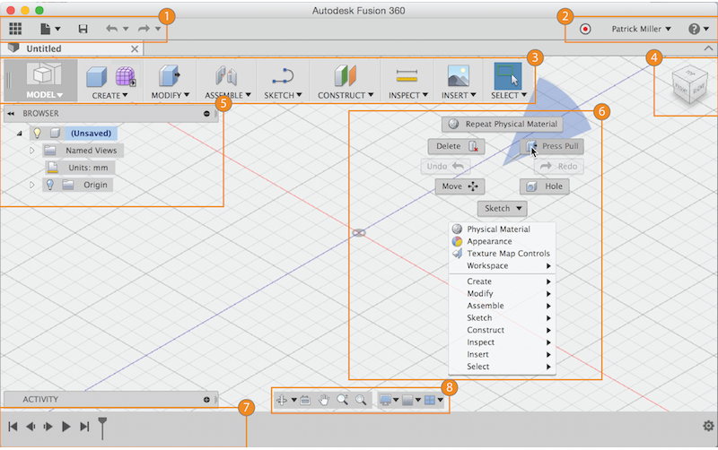
- Application bar: Access the Information Panel, file operations, relieve, undo and redo.
- Profile and assistance: In Profile, you tin control your profile and account settings, or utilise the help menu to keep your learning or get aid in troubleshooting.
- Toolbar: Apply the Toolbar to select the workspace you desire to piece of work in, and the tool y'all want to employ in the workspace selected.
- ViewCube: Use the ViewCube to orbit your design or view the design from standard view positions.
- Browser: The browser lists objects in your design. Utilize the browser to make changes to objects and command visibility of objects.
- Canvass and marking menu: Left click to select objects in the canvas (the space where yous brand your models). Right-click to access the marking carte du jour. The marking menu contains oft used commands in the wheel and all commands in the overflow carte.
- Timeline: The timeline lists operations performed on your design. Right-click operations in the timeline to make changes. Drag operations to change the society they are calculated.
- Navigation bar and display settings: The navigation bar contains commands used to zoom, pan, and orbit your design. The display settings control the appearance of the interface and how designs are displayed in canvas.
Footstep iv: Canvas Navigation
There are 3 ways to manipulate the view of your design:
- Navigation Bar
- ViewCube
- Cycle push button on a mouse
Navigation Bar

The navigation bar is positioned at the bottom of the canvas. It provides access to navigation commands. The menus on the right cease control Display Settings and Layout Filigree options.
To start a navigation command, click a push button on the navigation bar.
Navigation Commands
- Orbit: A set of commands that rotate the current view.
- Look At: Views faces of a model from a selected plane.
- Pan: Moves the view parallel to the screen.
- Zoom: Increases or decreases the magnification of the electric current view.
- Fit: Positions the unabridged model on the screen.
Brandish Settings
Set of commands that enables yous to specify desired visual style, visibility of objects, or camera settings, for example.
Filigree and Snaps
Commands that allow yous to specify increments, grid settings, and show / hide the layout filigree.
Viewports
Viewports are windows that display your design. You can show up to four viewports in the sheet at one time. Displaying multiple viewports allows you lot to piece of work in one view and see the changes from other photographic camera positions.
ViewCube

Use the ViewCube to rotate the camera. Drag the ViewCube to perform a gratuitous orbit. Click faces and corners of the cube to access standard orthographic and isometric views.
Mouse: Employ mouse shortcuts to zoom in/out, pan the view and orbit the view.
- Curlicue middle mouse button to zoom in or zoom out.
- Click and hold the middle mouse button to pan the view.
- Shift Key + middle mouse button to orbit the view.
Trackpad: If you have a Mac with a touchpad or an Apple Magic Mouse, you lot can apply multi-affect gestures to navigate the view.
Stride 5: Prototype-2-Surface Script
"Script" is shorthand for a bit of code that you can plug into the program to requite it a new tool that wasn't included past the software developer. At that place are dozens of scripts that allow you to do some pretty crawly things.
To translate a 2D bitmap image to a 3D surface for CNC milling, we're going to use the Image-two-Surface (updated 03 / 2018) script written by Hans Kellner.


The script is very simple. All it does is translate the value (level of lightness or darkness) of a bitmap image to the superlative of a point on a mesh surface. The white parts of an image will be the highest points, and the black parts will exist the lowest points. This script will work with whatsoever photograph, merely I find it's all-time to use grayscale images because information technology's easier to predict what information technology will look similar in 3D.
INSTALL THE SCRIPT
First, download the Zip file attached belo and unzip it in a location of your choice. I would propose keeping it some identify other than the Downloads folder, or any other folder that is regularly cleaned out.
To load the script in Fusion, follow these steps:
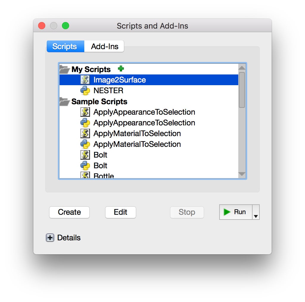
- First Fusion 360 and then select the Add together-INS > Scripts and Add together-Ins... menu particular.
- The Scripts and Add-Ins dialog will appear and display the My Scripts and Sample Scripts folders.
- Select one of the My Scripts folders, and so click on the + icon near the summit of the dialog.
- Locate the Image2Surface.js file in the folder you lot copied, select it, and click Open. The script should now exist installed and set up to be run.

Scripts and Add together-Ins Menu
Step 6: Utilize the Image ii Surface Script
RUN THE SCRIPT
After opening Fusion, I relieve the untitled file with a new name.
With my file saved, and the Workspace set to MODEL, I go to ADD-INS > Scripts and Add together-Ins... I select Image2Surface from the list and click Run.
If

Santa Cruz Canyons File: 288 X 288 PX
SETTINGS
When you've selected your image, click OK and you'll go the Image2Surface script dialog. Here's a breakdown of the settings and what they mean. At that place'south a lot of technical jargon that we won't get into here, but I find that a good identify to get-go learning nearly this kind of affair is to but play effectually with the settings and see what happens. The settings shown in the screenshot below seem to yield the all-time results. 
Yous may desire to capsize your image depending on what it is. When your settings are dialed in, click OK, and the script will make the surface. IMPORTANT: Export format must be set to OBJ in social club for the surface to be usable for CNC work subsequently.
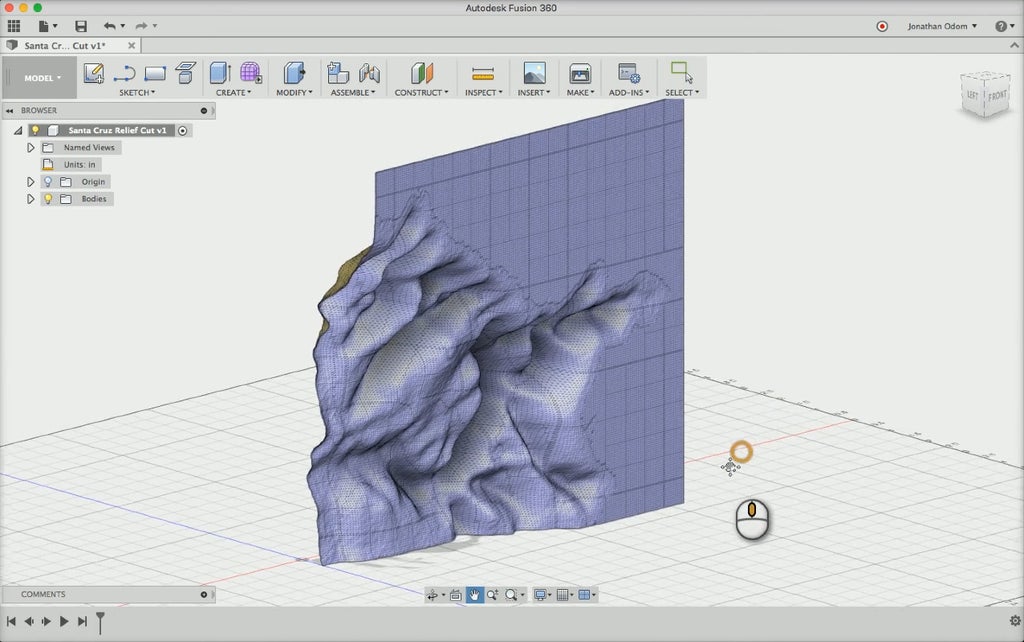
Mesh created by the Prototype-ii-Surface script by Hans Kellner
TROUBLESHOOTING
Is Fusion freezing or crashing when yous try to run the script? Chances are, your epitome is too big. Keep it under 300 X 300 pixels and it shouldn't be a problem. The smaller the image, the faster the processing.
NON-WORKING SCRIPT
If the script isn't behaving every bit described even though you followed the instructions, I would suggest looking at this thread on the Autodesk Knowledge Base of operations: https://noesis.autodesk.com/support/fusion-360...
Normally when a script isn't working, it'south because information technology wasn't installed properly.
Step 7: Catechumen Surface to T-Spline Geometry
The surface the script creates is a Polygon Mesh surface. This type of surface is made up of facets with edges and points. If you zoom in, you'll see that there are no curved surfaces.
This type of geometry can't exist used to make yard-code toolpaths, then we'll need to convert information technology to T-Spline geometry. A t-spline is a type of NURBS geometry that works with control points that affect a flexible surface.
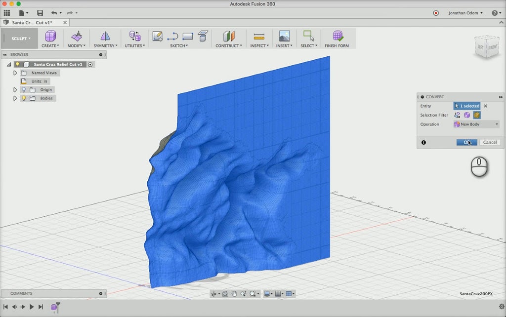
You lot're going to need a T-Spline geometry to create your CNC tool path, so click the CREATE > Create Form tool from the bill of fare. This tool takes you lot into the SCULPT workspace.
Adjacent, click UTILITES > Convert and select Mesh Trunk in the Choice Filter. Now click the mesh surface that the script created and click OK. Now it'south time to be patient and let the program exercise its work converting the surface to a T-Spline body- it might take a couple of minutes.

Click End Class and Fusion volition become dorsum to the MODEL workspace.
Identify THE SURFACE WITHIN A Block
In order to improve visualize what you're going to cutting out on the CNC, it's a good idea to create a solid class. First, select the surface in the Bodies folder in the BROWSER on the left-mitt side of the screen. And then Right-Click anywhere on the screen and select Motion from the carte.
Looking at the surface from the side, rotate information technology 90º so that the elevation of the surface is facing upward.
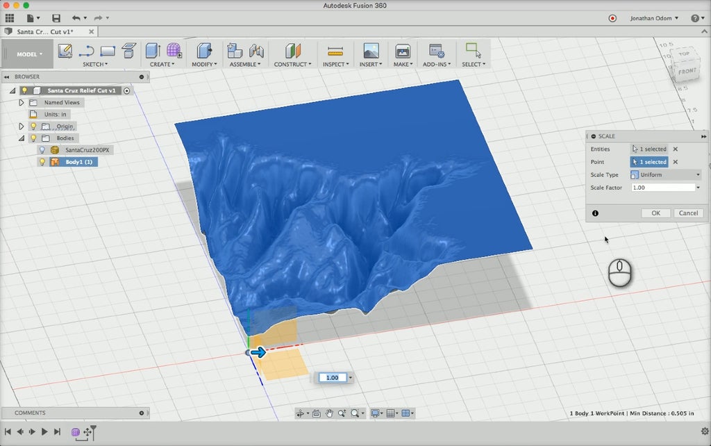
The size of the surface is based completely on the original bitmap prototype, and so at present you'll need to calibration it to fit the actual size of the slice y'all want to cut out. To do this, make certain the body is selected in the BROWSER and go to MODIFY > Calibration in the menu. Click Point and select the model origin.
NOTE: You may need to turn on Origin in the browser in order to encounter information technology.
Looking at the surface from the Top view, change the Calibration Factor so that the surface fits inside the size of the piece you want to cut out. I'm going to use a 3" 10 three" piece of wood, so I'm looking for a scale gene that will give me a SURFACE that'southward just slightly BIGGER than three" Ten 3". I can see how big it is on the layout grid.
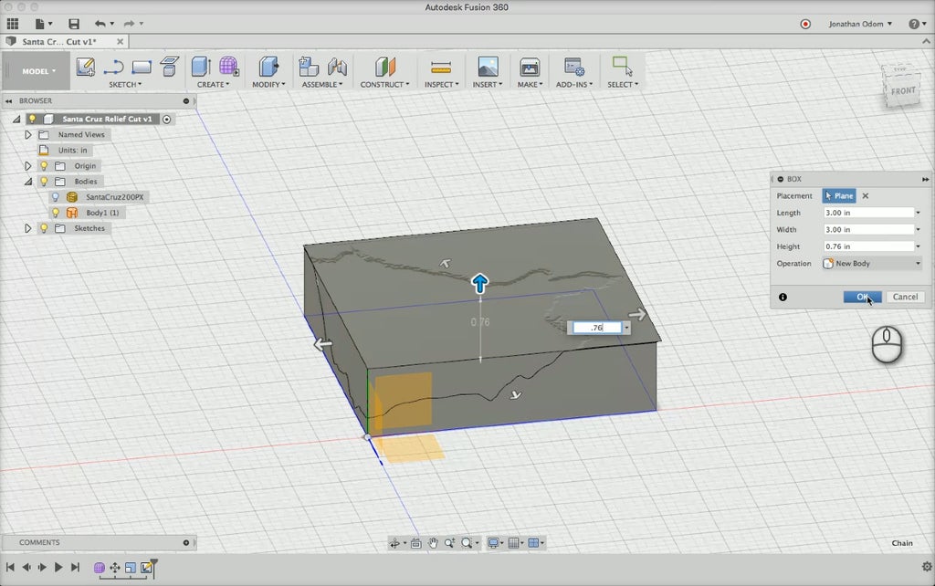
Now that the surface is in place, create a box to represent the material to be cut out. I'yard using a 3" X iii" X .76" foursquare, then I go to CREATE > Box and click the model origin equally my starting indicate. The box command asks for a width, a depth, and a top, which you tin enter by typing a number and pressing Tab.
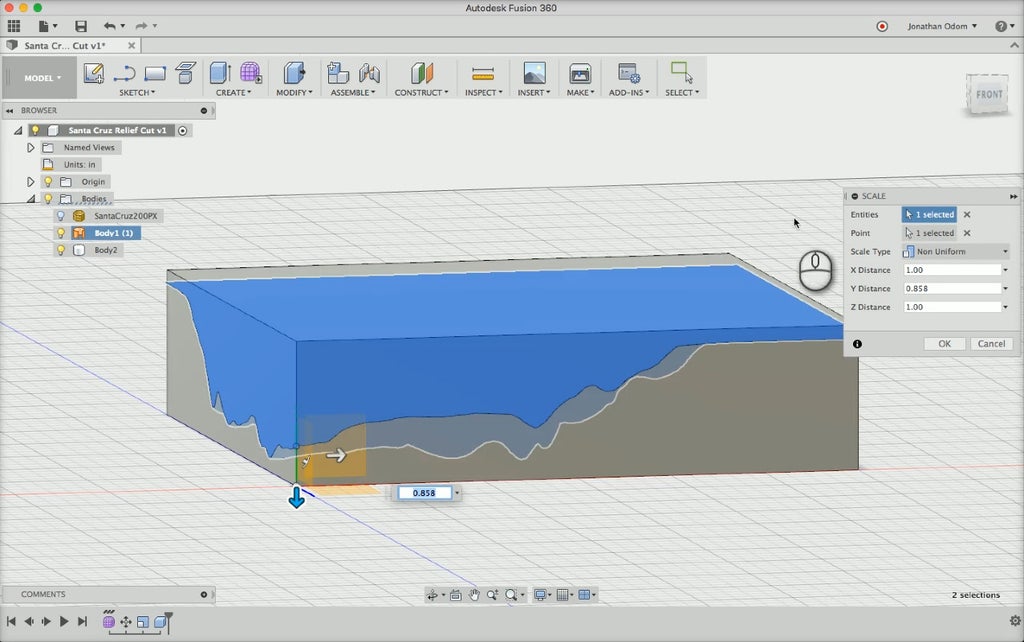
I tin can meet that the surface to be cutting is actually taller than the material to be cut, so not I demand to calibration the surface down in the Y dimension. I use the Scale tool over again, and change Scale Blazon to Not Compatible. This option will let y'all calibration in any dimension independently. For Y Distance, Choose a number that gives you some breathing room for the surface to fit within the block.
To move the surface closer to the superlative of the block, Right - Click > Motility the surface upwards in the Y direction so that it'south merely below the superlative of the block.
CREATE A SOLID SURFACE
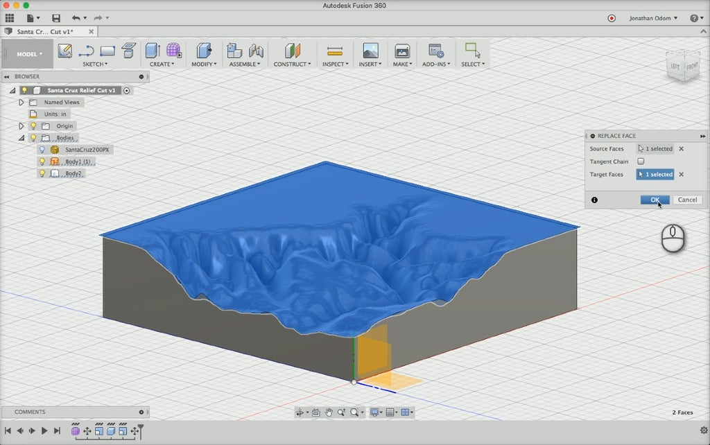
With both the block and the surface in place, get to MODIFY > Replace Confront. Like every other tool in Fusion, it tells you what it needs to piece of work. First, select the Source Face, which in this case is the top surface of the block. And so, click Select under Target Faces and select the surface you lot but converted from the original mesh. Click Okay, and then turn off the original body in the BROWSER and y'all'll see the finished surface that you'll be making on the CNC.
Prove US WHAT YOU GOT
If you gave it a try, delight mail service your results hither!
84 People Fabricated This Project!
Recommendations
Source: https://www.instructables.com/3D-CNC-Relief-Sculpture-Fusion-360/
0 Response to "turn a drawing into a 3d model fusion 360"
Post a Comment